
This is the first of a series of devices which we will be developing in order to help home owners take control of their homes in innovative ways. While developing these devices, our main concerns are:
- Privacy: Most devices that we find on the market require that you create an account on different websites and share a number of private data with these websites. The devices we will develop work within your private network and can be controlled with your cell phones without the need for external accounts or authorising any third party to access your private network.
- Flexibility: We will show you how to adapt the devices to fit your own needs or re-purpose them for a completely different task. The Pool Cover Opener that we describe in this article can be used as a remote control to open your pool cover or can be reused to open your garage door or the front gate in the same way.
- Simplicity: For hobbyists who like to tinker with electronics and/or programming, we offer them the design schematics for our devices and provide the basic source-code to completely reprogram the devices for different purposes. The designs are very simple in nature and can be the base for building more complex devices at low cost.
Here is what the final device will look like:
 |
| Pool Cover Opener |
You can purchase the completed Pool Cover Opener device for 20 euros by visiting the online store to the right of this page.
In this article, we will delve more deeply into:
- Designing an electronic circuit with the ESP8266 microcontroller with WiFi module
- Initial programming of the ESP8266 with a firmware that allows further programming over the air (OTA)
- Controlling a mechanical relay using one of the pins of the microcontroller
- Remote controlling the microprocessor using UDP
For the sake of brevity, some items that will be left for a separate article:
- Connecting the device to Google Home
- Designing the printed circuit board and submitting it for production
Electronic Circuit
The electronic circuit is made of 3 parts:
The Power Supply
The Micro-controller
The Mechanical Relay and its drivers
Power Supply
Requirements:
Input voltage: Up to 36V AC/DC
Outputs: 5V DC to drive the relay, 3.3V DC to drive the ESP8266
The design is pretty standard and can be found in a number of online resources. The one we are using is based on the common MC34063ADR switching voltage regulator. This will give us the 5V output voltage from up to 40V of input voltage.
The computation of the output voltage is as follows:
Vout = 1.25 x (1+ R23/R22) = 1.25 x (1+3) = 5V.
To generate the 3.3V output, we can use either the NCP1117ST33T3G Low Dropout Regulator or the MIC5219-3.3YM5. The advantage of the MIC5219 is that it takes much less PCB space and is cheaper but can handle only 500mA of current whereas the 1117 can handle up to 1A.

Microcontroller
Requirements:
Interface connector to do the initial programming of the microcontroller
A single output pin to drive the mechanical relay

The following pins are needed to program the ESP8266 through the J3 connector:
Pin 9: Ground
Pin 8: 3.3V Vcc
Pin 1: Reset
Pin 15: RxD (data receive)
Pin 16: TxD (data transmit)
Pin 12: Flash or Echo pin
We will look at initial programming of the microcontroller under the section "Programming our Board."
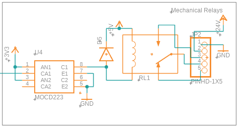
Relay Circuit
The relay we are using in our design is an Omron G5Q series relay with the following characteristics:
Input voltage: 5V, minimum voltage: 3.75V
Input current: 80mA @ 5V, minimum to activate: 60mA
The ESP8266 cannot drive the relay directly for two reasons. One is that the micro-controller can only deliver 12mA on each pin whereas the relay requires 60 to 80mA. The second is that the micro-controller needs to be isolated from the relay coil and the output circuitry.
There are various ways to drive the relay while protecting the micro-controller most of which are based on an opto-coupler followed by one or more transistors to amplify the current. One solution is to use an opto-coupler with Darlington outputs to avoid adding additional transistors.
An important parameter to take into consideration when selecting the opto-coupler is the minimum Current Transfer Ratio (CTR). The opto-coupler should be amplify our input current of 12mA max to the 60 to 80mA current required by the relay. This is a minimum CTR of 500% to 700%.
The LTV-815 is a low-cost opto-coupler that satisfies our requirements with 600% minimum CTR and output current of 80mA. The MOCD223 is a dual-channel option with similar characteristics. Although more expensive, the MOCD223 gives us the option to easily add a second relay if needed.
Reviewing the parameters of our circuit, we have:
Input current = (Micro-controller voltage - Opto-coupler LED voltage) / series resistance = 2.2V / 220Ω = 10mA
Output current = (Input voltage - Transistor voltage) / Relay Coil Resistance = 4.1V / 63Ω = 65mA
As the output current is very close to the minimum required by the relay, we can adjust our power supply to provide a slightly higher voltage of 5.2 or 5.3V without affecting the rest of the circuit.
Programming the Board
Tools needed for Programming
The most commonly used tools for programming the ESP8266
- Arduino IDE: A free environment to experiment with the ESP8266 or develop very simple applications
- Visual Studio Code with either:
PlatformIO extension
Both of these extensions are free and provide with more complete development environment than the Arduino IDE
- Visual Studio Community Edition with Visual Micro: This is paid plugin for Visual Studio with a number of interesting options, suitable for professional developers
Initial Programming through the USB or Serial Port
Unless the ESP8266 is already pre-programmed or if you lose access to the micro-controller during testing, you need to connect your board to your PC using a serial cable or a USB cable with a USB to serial converter and add some simple circuitry to your board.
An easier solution is to use a board such as the low-cost Node MCU and connect the pins of the Node MCU to the pins of the ESP8266 as follows:

You should also disable the ESP8266 of the Node MCU by connecting the EN pin to ground so that it doesn't conflict with your own ESP8266 micro-controller.
Here is an example of how the Pool Cover Opener board is connected to the USB port of the PC through the Node MCU for initial programming:
 |
| Pool Cover Opener connect to Node MCU for programming |
Comments
Post a Comment